


* Integrated TCP/IP protocol stack * +19.5dBm output power in 802.11b mode
* Supports antenna diversity * Integrated low-power 32-bit MCU
* SDIO 2.0, SPI, UART * Wireless SoC
* Has GPIO, I2C, ADC, SPI, PWM * Maximum frequency is 80MHz
* 64k bytes of instruction RAM * 96k bytes of data RAM
* 64k bytes of boot RAM * RISC architecture
* Integrated PLL, regulators and power-management units
Circuit and working
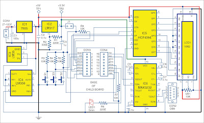
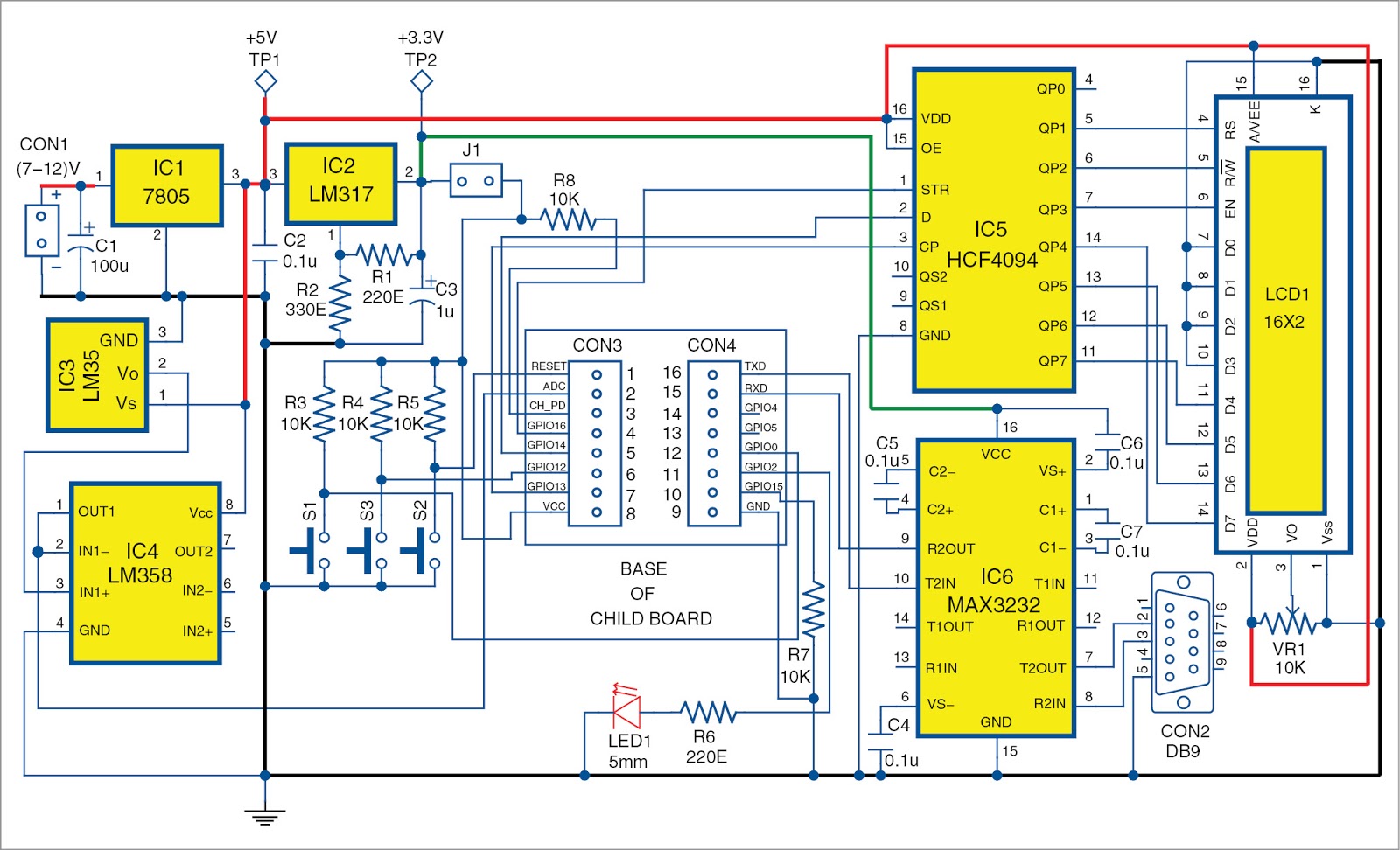
Circuit diagrams of the main board and child board are shown in Figs.We have used ESP8266 as a stand-alone device. Supply voltage for the Wi-Fi module is 3.3 volts. Child board is to be mounted on the main board.
CON2 is used for COM port interface for connecting the module to a PC and the module is programmed using a USB-to-serial converter. If physical COM port is available on the PC, USB-to-serial converter is not necessary.
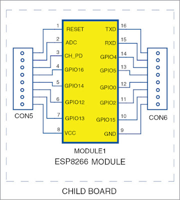
ESP8266 module has 16 pins. Pin 1 (RESET) is connected to 3.3V through resistor R5 and push-button S2 is provided for manualreset. Programming
Circuit and working
CON2 is used for COM port interface for connecting the module to a PC and the module is programmed using a USB-to-serial converter. If physical COM port is available on the PC, USB-to-serial converter is not necessary.
mode pin 12 (GPIO0) is connected to 3.3V through R3, and S1 is used to bring the module to programming mode. Pin 3 (CH_PD) is connected to 3.3V through R8.
ESP8266 also integrates a general-purpose 10-bit resolution ADC (pin 2). It is typically used to measure voltage from the sensor or battery. It cannot be used when the chip is transmitting, otherwise, voltage may be inaccurate.
All digital input/output (I/O) pins are protected from over-voltage with a snap-back circuit connected between the pad and the ground. Snap-back voltage is typically 6V and holding voltage is 5.8V. This provides protection from over-voltage and ESD. Output devices are also protected from reverse voltage with diodes. LED1 is connected to pin 11 (GPIO2). Pin 6 (GPIO12) is connected to 3.3V through R4 and provided with a push-button (S3) for debugging purposes.
Every supplier of Wi-Fi modules follows a different pattern for output pin arrangement. So no standard PCB pattern can be followed. Readers of EFY can design their own PCB. Authors of this article have purchased ESP8266 module model no. 4255 from Sunrom Technologies and the PCB is designed to suite their requirement.

An application has been implemented to measure room temperature using LM35 temperature sensor and an LED control (on/off) using a Web browser. LM35 is a calibrated temperature sensor, whose sensitivity is 10 milli-volt/1°C, but one can build customized projects also.
ESP8266 can be used in home automation, mesh networks, industrial wireless control, IP cameras, sensor networks, smart power plugs, baby monitors, wearable electronics, security ID tags, position system beacons and location-aware devices.

The software is simple. setup() routine initalises the hardware by configuring the serial port, GPIO2 pin as output and GPIO12 as input. setup-WiFi() routine configures the wireless section. loop() routine handles requests from the client.

Function size_t send Programmer,sends data to the client.array IN[ ] corresponds to the Web page, image[ ] array corresponds to EFYLOGO and
ESP8266 also integrates a general-purpose 10-bit resolution ADC (pin 2). It is typically used to measure voltage from the sensor or battery. It cannot be used when the chip is transmitting, otherwise, voltage may be inaccurate.


Component List

Software
In this project we have used Arduino IDE for compiling and loading programs. ESP8266 community has developed a suitable plugin for ESP8266 to use with Arduino IDE. The plugin supports three types of ESP8266 Wi-Fi boards. These are generic ESP8266 board, node MCU ESP8266 board and OLIMEX ESP8266 development board.
Installing the ESP8266 Arduino Addon. Install Arduino IDE 1.6.5 version.Launch Arduino IDE and open preferences window from File ->Preferences option
Open Boards Manager from Tools -> Board: Arduino Uno -> Boards Manager and scroll down to find ESP8266 by ESP8266 Community. Highlight the field and Install button will appear. Click it. The process will take nearly 30 minutes with an Internet connection.

Function size_t send Programmer,sends data to the client.array IN[ ] corresponds to the Web page, image[ ] array corresponds to EFYLOGO and
ES[ ] array corresponds to the module.
Arrays are created using file-to-array converter software hexy. It is free and can be downloaded from the Internet. While creating the array, remove image extension jpg for decoding purpose. All jpg files have been included in this article.
Suitable routines are included to change and store SSID and password. After configuration of ESP8266 is done for Wi-Fi, an 8-bit serial shift to parallel-shift register program using HCF4094 is used for LCD interface.
PCB and component layout
An actual-size, single-side PCB for the main board is shown in Fig.
An actual-size, single-side PCB for the child board is shown in Fig.


Install USB-to-serial UART converter driver software and perform loop-back test.Select Generic ESP8266 Board Module from ToolsBoard: Arduino Uno. Arduino IDE will accept your board and you can fuse the program using Upload button. To fuse the program into the module, connect the COM port (CON2) of the main board to your PC through serial-to-USB converter and select as well as note down the emulating virtual COM port number.


Power-on the main board.
Holding Program button S1 (GPIO0) down, press Reset button (S2) down. Release Reset and then release S1 (GPIO0) button. Now ESP8266 will enter into program mode. Click Upload button and the program will get compiled and generated bin file will load into the module.

Power-off the main board and power-on your Wi-Fi dongle. Open hyper-terminal on the PC with baud rate 115200 and select COM port. Hold S3 down and power-on the main board. You will get a prompt for entering SSID and password. Release switch and enter SSID and password of your Wi-Fi network separated by comma. Click Enter. SSID and password will be stored in the EEPROM.
When Wi-Fi is connected, IP address of ESP8266 module will be displayed in LCD1. Launch the browser with the IP address. You will get a Web page as shown in Fig.Buttons marked as LED ON and LED OFF are for switching on and off LED1. Appliances like fans and motors can be switched on and off with a suitable relay driver circuit using opto couplers connected to pin 11 (GPIO2). Status of pin 6 (GPIO12) and temperature readings are displayed using AJAX scripts without refreshing the entire Web page.
Arrays are created using file-to-array converter software hexy. It is free and can be downloaded from the Internet. While creating the array, remove image extension jpg for decoding purpose. All jpg files have been included in this article.
Suitable routines are included to change and store SSID and password. After configuration of ESP8266 is done for Wi-Fi, an 8-bit serial shift to parallel-shift register program using HCF4094 is used for LCD interface.
PCB and component layout
An actual-size, single-side PCB for the child board is shown in Fig.


Power-on the main board.
Holding Program button S1 (GPIO0) down, press Reset button (S2) down. Release Reset and then release S1 (GPIO0) button. Now ESP8266 will enter into program mode. Click Upload button and the program will get compiled and generated bin file will load into the module.

When Wi-Fi is connected, IP address of ESP8266 module will be displayed in LCD1. Launch the browser with the IP address. You will get a Web page as shown in Fig.Buttons marked as LED ON and LED OFF are for switching on and off LED1. Appliances like fans and motors can be switched on and off with a suitable relay driver circuit using opto couplers connected to pin 11 (GPIO2). Status of pin 6 (GPIO12) and temperature readings are displayed using AJAX scripts without refreshing the entire Web page.
No comments:
Post a Comment